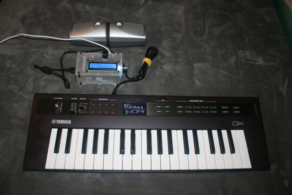
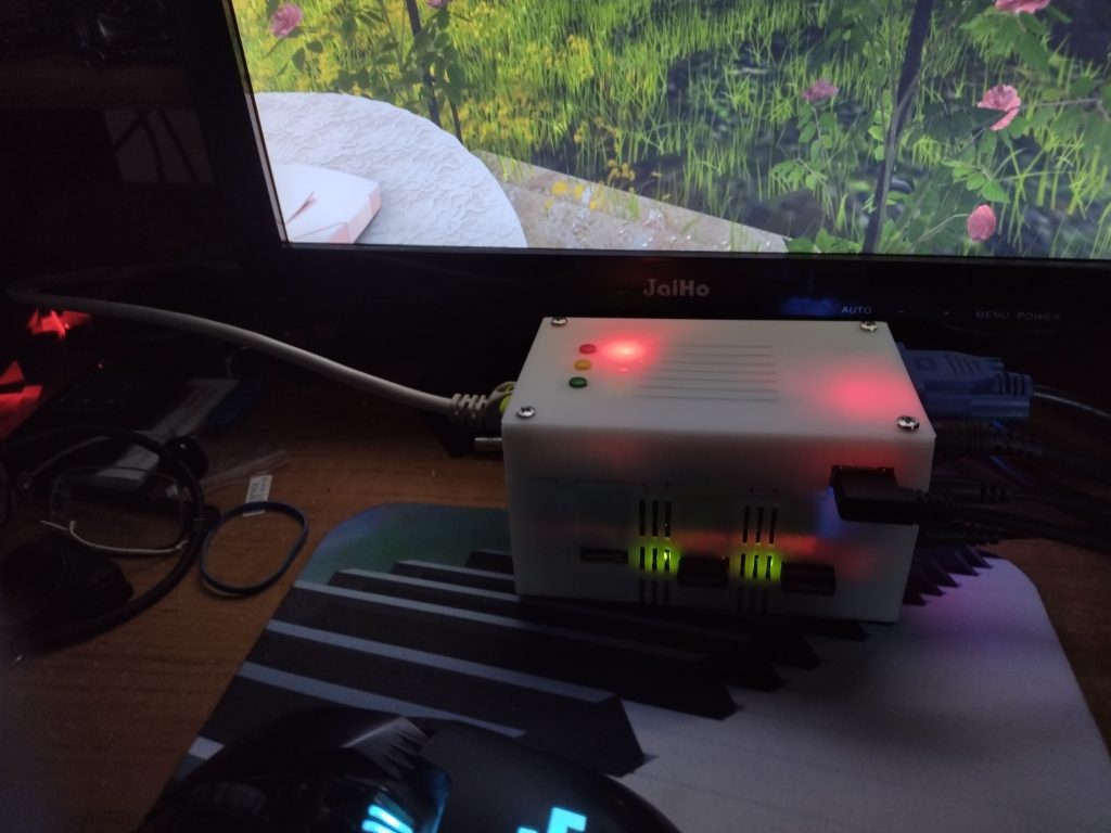
So I promised a little bit ago that I’d take a shot of using the MiniDexed with a keyboard and speakers. Here we are – I have my Yamaha Reface DX connected via USB to the MiniDexed and able to play sounds from MIDI to speakers (I’d recommend a small amp, the output without an amp is quiet).
Yamaha Reface DX connect by USB to MiniDexed Synth and Speakers
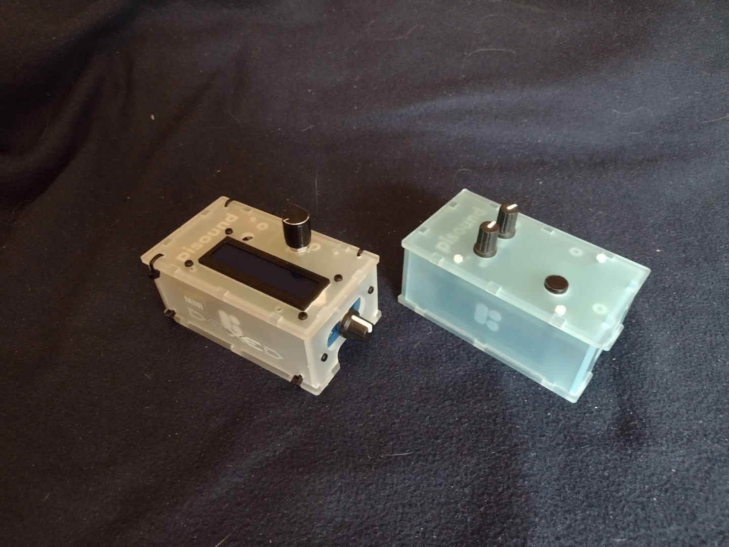
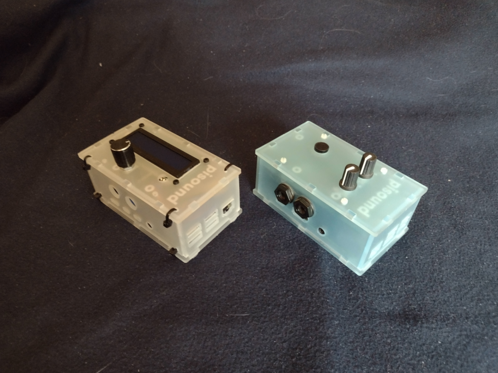
I did take pictures with the pisound project and MiniDexed project together. You can see what I did to the project box by comparing the original pisound and my MiniDexed. Note that the pisound uses a Raspberry Pi 3b+ and my MiniDexed uses a Raspberry Pi 4b (8 GB). The pisound case I got for the MiniDexed comes with different panels for the different versions of the Raspberry Pi.
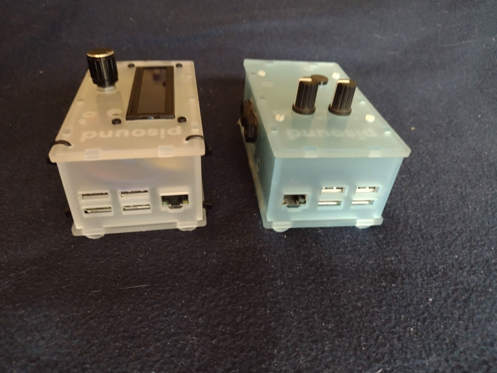
The MiniDexed on the left, the pisound on the right, view from the top.
The MiniDexed on the left and the pisound on the right. Here the MiniDexed has the LCD panel and Encoder Knob on the top, and the LCD Contrast Knob on the Right Side. A hole was drilled for the Encoder Knob as you can see on the pisound there is no hole there. You can see the Zip Ties I used in all the pictures.
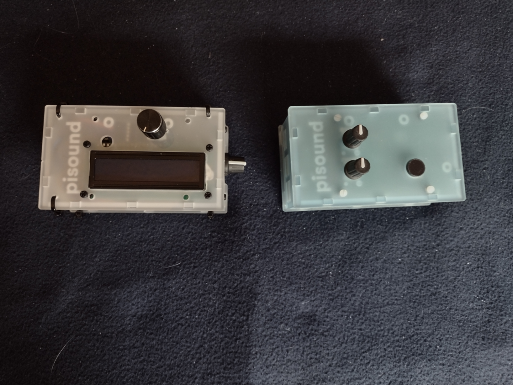
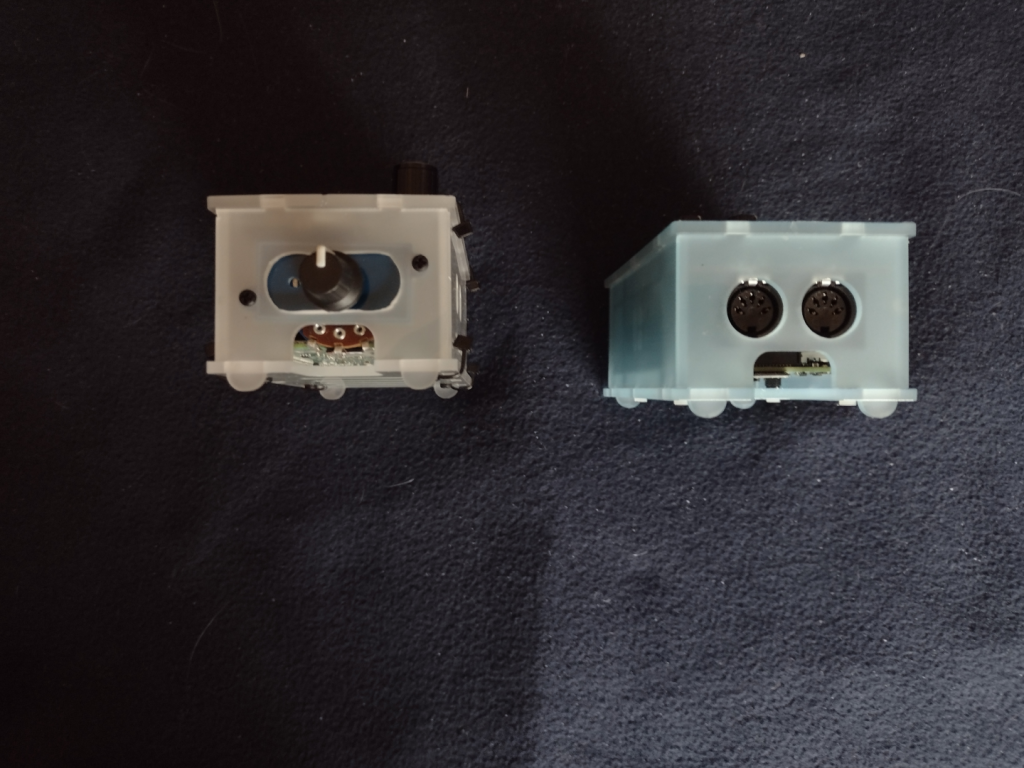
The MiniDexed on the left, the pisound on the right, view from the front.
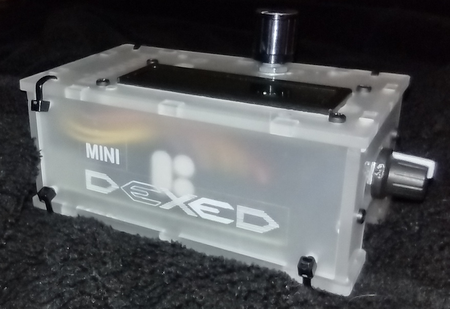
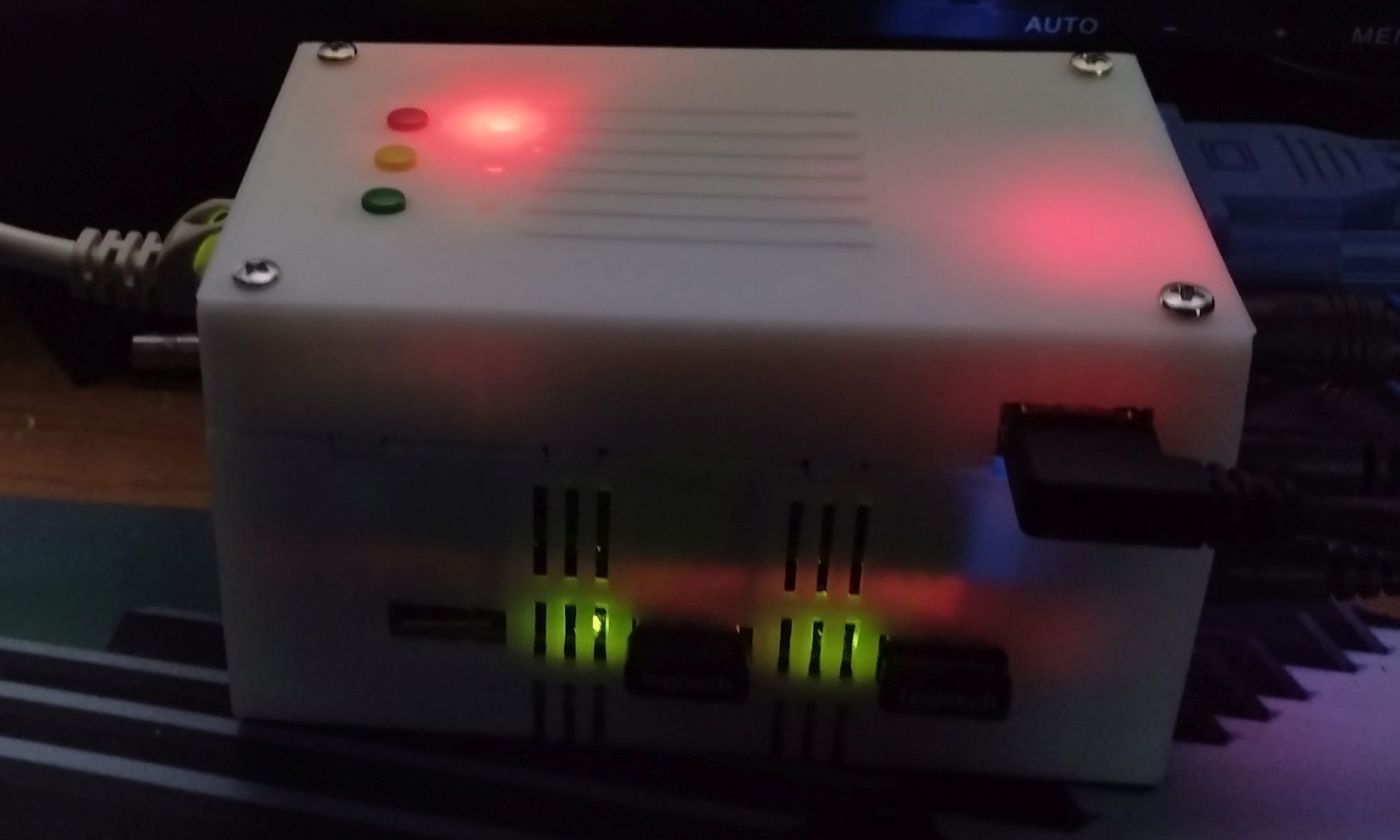
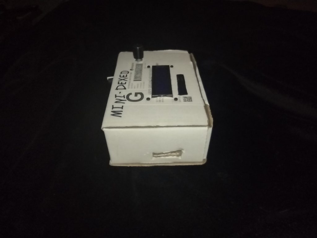
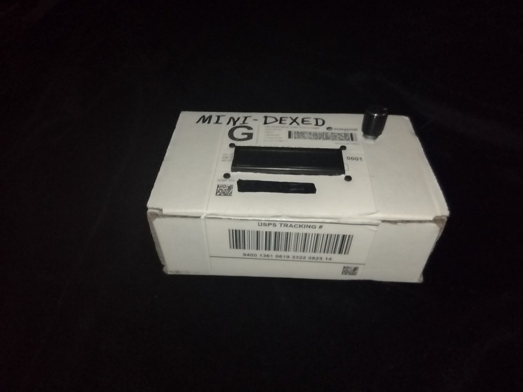
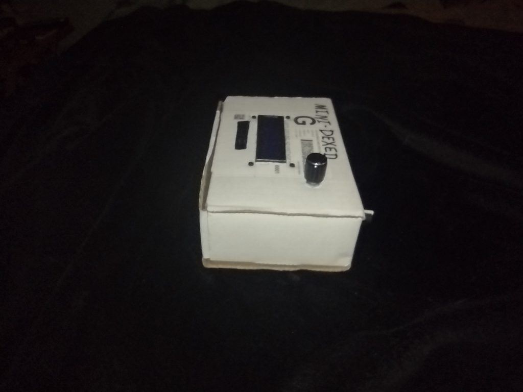
On the MiniDexed I added a pair of labels to show the MiniDexed Logo. Originally I was going to use Black ink. But I didn’t have any black-on-clear label tape, only the white-on-clear. It works ok, but not as well as I wanted. I got the logo from the Facebook MiniDexed page. I like their logo. You can see the LCD Contrast Knob on the right side of the MiniDexed. There are only three Zip Ties on the front face because the LCD Module Circuit board is in the way. I had to put the LCD Module close to the Front side so I could squeeze the Encoder Module at the back side.
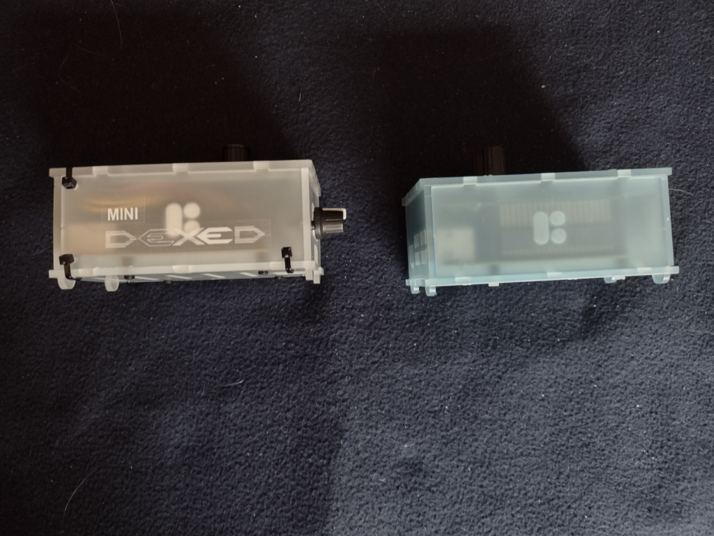
The MiniDexed on the left, the pisound on the right, from from the right side.
The LCD Contrast Knob is attached in the modified MIDI ports holes. I cut out the bridge between the two MIDI port holes to make one larger hole. Then I used a filler plate from the RC2014 project case. The potentiometer for the contrast is large and you can see it through the micro SD Card Slot window. Taking out the micro SD card on the MiniDexed will require some disassembly to get to it. On the pisound, the micro SD card is accessible.
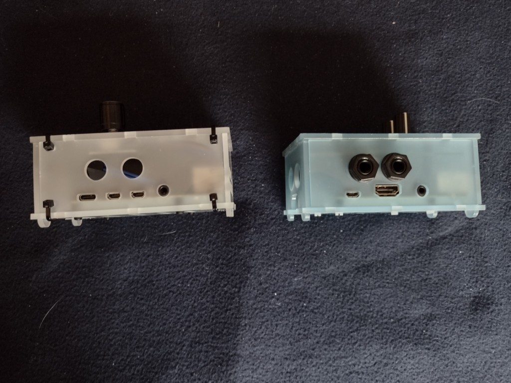
The MiniDexed on the left, the pisound on the right, from the back.
The differences between the Pi3b and Pi4b are somewhat obvious here. Note that the 6.5mm audio jack ports from the pisound are not used on the MiniDexed. There really isn’t room inside the case for the Audio DAC circuitry because of the LCD Module and the Encoder Module.
The Pi4b has a USB C port for power, two micro HDMI ports for video (not used for the MiniDexed), and a 3.5mm port for the Audio. On the Pi3b+ for the pisound, there is a micro-USB for the power, a single full size HDMI and a 3.5mm audio jack (neither is used on the pisound). The 3.5mm audio jack on both the Pi4b and the Pi3b+ include a forth conductor for composite video. On the Pi3b+ and older Pi models, the audio was considered inferior, which is why the pisound has the Audio DAC circuitry and the two (Stereo In and Out) 6.5mm jacks.
The MiniDexed on the left, the pisound on the right, from the left side.
I had to abandon the straight on photo of the side panel for the left side because of the LCD Contrast knob on the right side of the MiniDexed. This shows another difference between the Pi3b+ and the Pi4. The Ethernet port swaps sides with the USB ports.
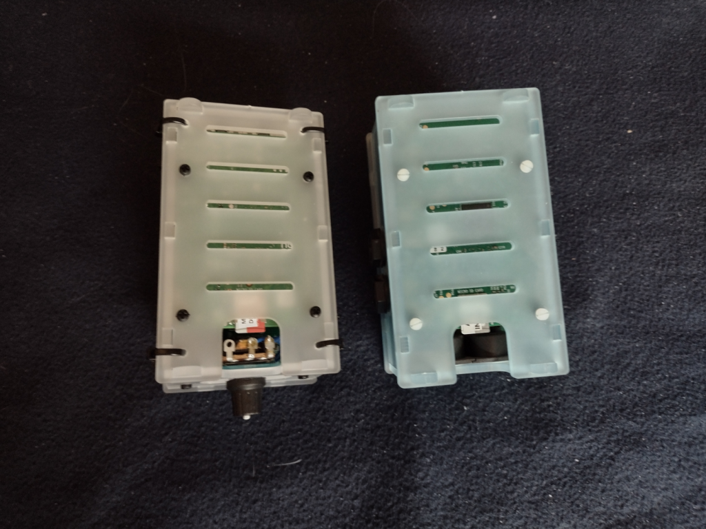
The MiniDexed on the left, the pisound on the right, from the bottom.
From the bottom you can see how the MiniDexed LCD contrast knob potentiometer takes up valuable space needed to access the micro SD card. I’ll have to cut out all the Zip Ties to make changes to the micro SD card. I will consider replacing that potentiometer with a smaller potentiometer if I ever need to get to the micro SD card.
The MiniDexed on the left, the pisound on the right, from the top front right corner.
This is kind of a “glamour shot” of the two projects showing off the top, front, and right sides.
The MiniDexed on the left, the pisound on the right, from the top left back corner.
The final shot of the two projects showing off the top, left, and back sides.
The MiniDexed is a bit of a tight fit into the pisound project case, but it works, and that is the point.
I’ve posted about my miniDexed project a couple of times before (Here and Here). I finally got my real miniDexed Project Box for it completed. It turned out well. I did have to buy a coping saw so I could cut the LCD panel hole. I also needed to drill out holes for the Encoder/Button knob, and for the LCD Contrast knob. And then a bunch more holes for the Zip Ties to hold the box together.
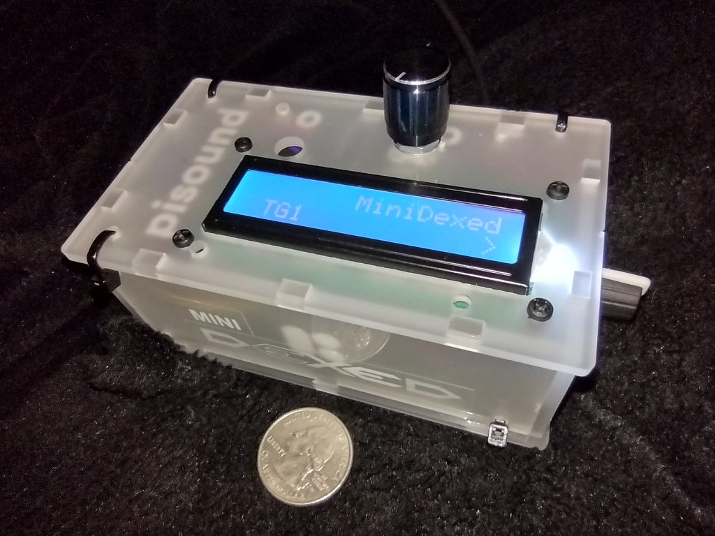
MiniDexed Yamaha DX7 emulator in it’s pisound project box. Quarter coin for scale.
I put together a little logo from the one used on the MiniDexed Facebook group and fixed that to the side of the project box. I really wanted black ink on the label, but I didn’t have any Black-On-Clear label tape. It’s actually two labels, the MINI on a short strip and then the DEXED in a larger “font” (not really a font, it isn’t even actual text, just a PNG of the text). On the top is the Encoder/Button knob. On the right side in the picture is the LCD Contrast Control knob. Around the side to the left are the Raspberry Pi I/O ports, 4 Type A USB (two USB3 and two USB2) and the Ethernet port. On the back side are the two Micro-HDMI video ports, a 3.5mm audio jack (with composite video), and the USB Type C for power.
I chose the Raspberry Pi 4 8GB model because the audio on the combined Audio/Composite video jack is supposed to be better than it was on the previous Raspberry Pi models. It is better, but an actual DAC sound module would be better still. But the DX7 wasn’t the cleanest sound, so there is that, too. The pisound that I have uses a Raspberry Pi Model 3 model with a special Audio board to avoid the sound issues, and a MIDI board. I didn’t try to add MIDI to my miniDexed, though I think others do. I will depend on USB MIDI. I did test that with my Yamaha Reface DX (Yamaha’s modern mini FM Synth). I’ll need to get a shot of the Yamaha Reface DX and the miniDexed together.
I’ll take some shots of the miniDexed and the pisound side by side for a comparison in a future post. The pi sound is a cool idea. I haven’t really taken advantage of it yet, and I’ve had it a long time – at least by October 2018.
One thing about the miniDexed is that it is really eight DX7 engines running together. Like a TX816
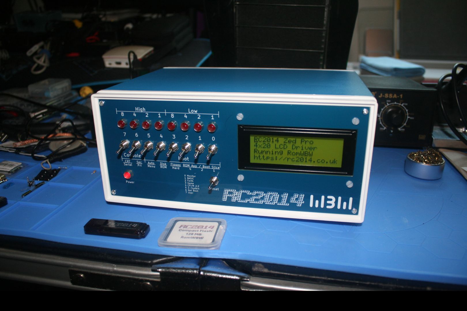
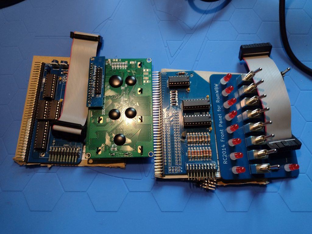
I received the “Front Panel” and “Rear Panel” Kits for my RC2014 Z80 Computer. These panels are specifically designed for the Blue Box 110x250x190 mm project case, which I had purchased even before I got the initial kit to create the RC2014. I spent the last few days soldering and assembling the panels.
The left side is the LCD Driver Module and and LCD Display and the right side is the Front Panel I/O module and the actual Panel for the front of the case.
You can see little tabs poking up through the back of the LCD panel. Under the little interface board that converts the 2×20 ribbon connector to the 16 pin the module needs is a tab that poked up into the pins of the little interface. It caused problems and I had to clip off that one tab. The Front I/O panel was also a problem, I soldered its ribbon cable header to the wrong side of the board, I had to desolder the header and flip it around behind the front panel so the ribbon cable could connect. My reading skills must be slipping. Though I don’t think the instructions mentioned the tabs on the LCD Display poking into the pins of the cable header.
There was a good bit of head scratching before I fixed those problems. But in the end, the front panel I/O and LCD Display are working well.
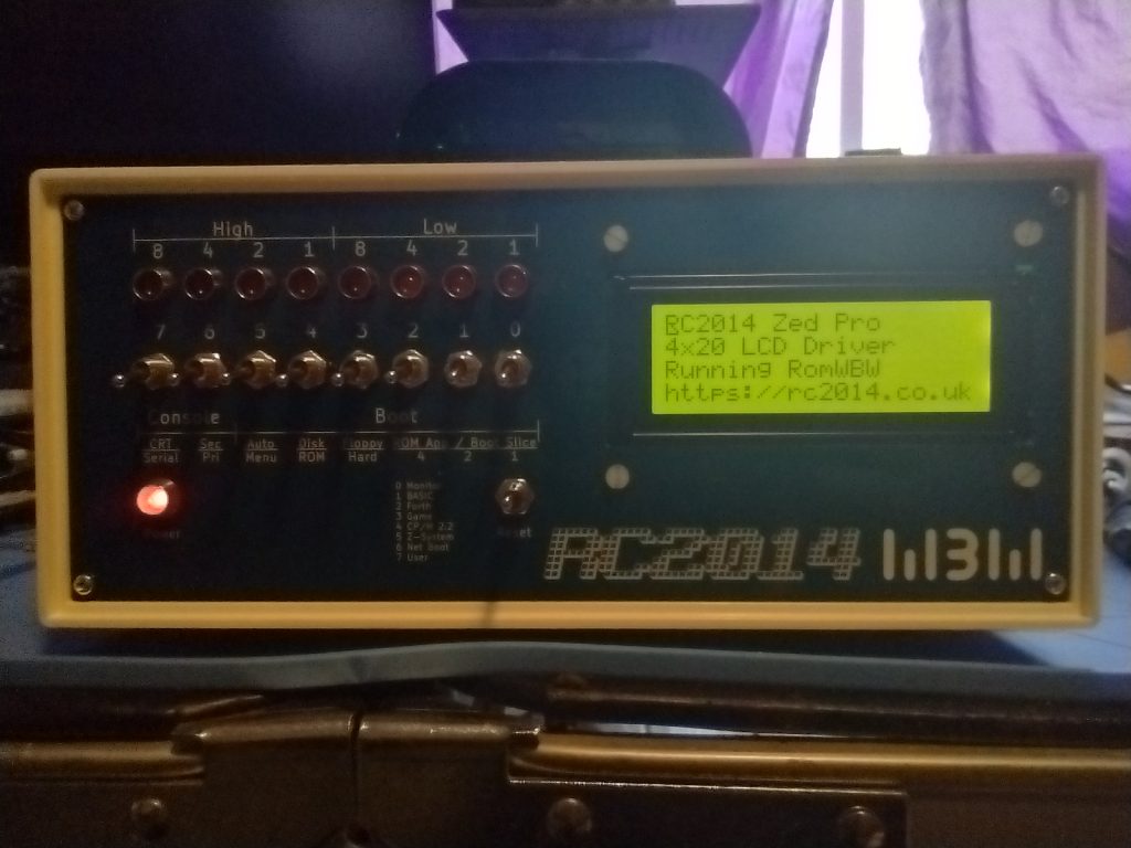
The switches on the Front Panel I/O control the boot up. There are several choices for how to boot.
First is the Small Computer Monitor, a program that allows direct access to the CPU registers and memory.
Second is a version of Microsoft BASIC for 8080 (and Z80) microprocessors. This would be similar to how many 1970s and 80s computers would boot straight into the BASIC language interpreter (Such as the Commodore 64).
Third Boot option is a FORTH Language Interpreter. I have no idea how to use FORTH, at least at the moment.
The Fourth Boot option is a simple game called 2048.
The Fifth boot option is CP/M 2.2, Digital Research’s famed operating system for personal computers of the late 1970s and into the 1980s and that a version of was offered to IBM for the IBM PC. But Digital Research didn’t like the restrictions IBM wanted (and which Microsoft found a way around when the licensed MS-DOS to IBM).
The Sixth option is Z-System, an enhanced version of CP/M for the Z80 CPU (and the one I use the most).
The Seventh is a “Net Boot” which won’t work since I don’t have the RC2014 on the network.
And the final (eighth) front panel option is a User ROM boot, but I haven’t put in a User ROM so no booting from it either.
The Front panel also has an option to boot from the hard drive (in my case a Compact Flash drive like I have in my Canon EOS DSLR). There are 5 “slices” to boot from the current hard drive.
Slice 2.0 boots CP/M-80 v2.2
Slice 2.1 boots ZSDOS v1.1
Slice 2.2 boots ZSDOS v1.1 (yup, I’m wondering if I messed something up)
Slice 2.3 boots CP/M-80 v3.0 with Banked Memory
Slice 2.4 boots ZPM3 with Banked Memory (compatible with CP/M+)
I made a second Compact Flash (CF) for learning how to customize the system. I’m still using the original Compact Flash drive that came with the kit, though. The second CF drive has several Infocom Games, like Zork, or Hitchhhiker’s Guide to the Galaxy, the classic Colossal Cave Adventure, and a few others. I also have HiTech-C and z80ASM programming tools, WordStar and ZDE, and stuff I’ve already forgotten.
The install of the Rear Panel Kit was simple. I got the blank version, it has blank cover for the holes where cables and connectors will eventually go. I’ll get those as I need them. Things like the FDTI adapter, and audio ports, maybe a video port, and so on.
Next up? I think a sound card, probably this one Why-Em-Ulator.
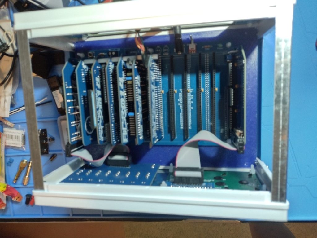
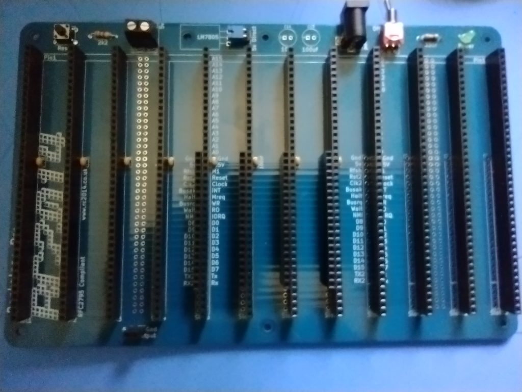
So first, before revealing if the thing works or needs more work, the first part of the update is that I finished the Backplane Pro. The Backplane Pro has 12 40-pin slots for the modules. It took a while to solder in 12 40-pin headers, 4 20-pin extended headers (the number of extended headers depends on how many extended bus modules you’re using. I have three at the moment, but I put in four), and a number of other small parts, a couple resisters, a power switch, power LED, a power jack, a reset button, and so on. I didn’t count all the solder points, At least 580 solders. I might have mentioned I’m a slow solderer; it took me most of the day.
The RC2014 Backplane Pro
Then I buzzed it out (using continuity testing of my Multi-Meter Oscilloscope, a ZOYI ZT-703S). I made sure all the header points had the signal they should, and didn’t have bleed over they shouldn’t. That took a while too. When I finished that, and did not find problems, I applied 5 volts to the power jack and checked the power LED did light, and the +5 and GND points all showed the power.
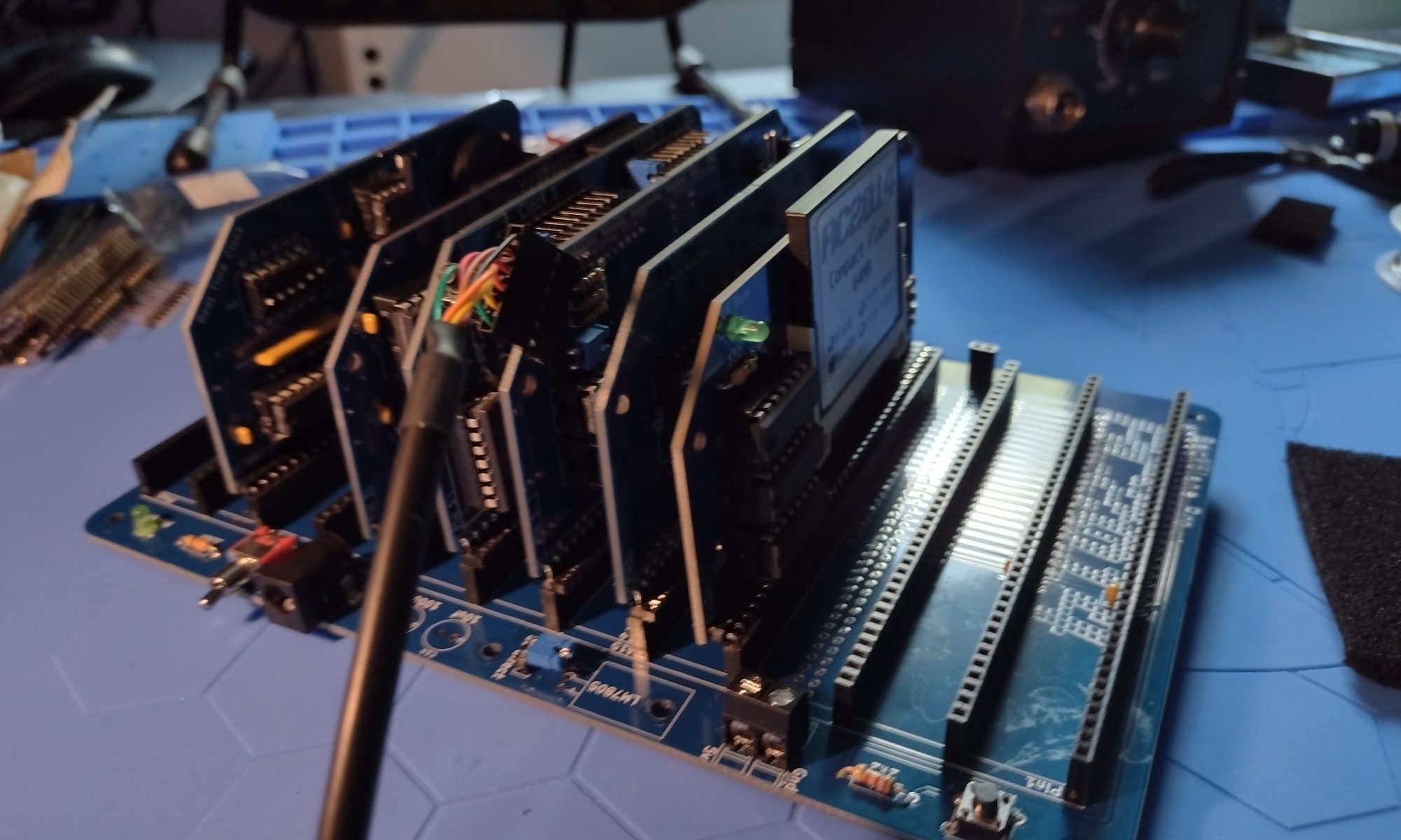
Fairly sure the backplane was good I went about checking the module circuit boards. I put them one at a time in a slot on the backplane and checked that power routed cleanly to the points in the sockets (without the integrated circuits plugged in). Everything looked good there too.
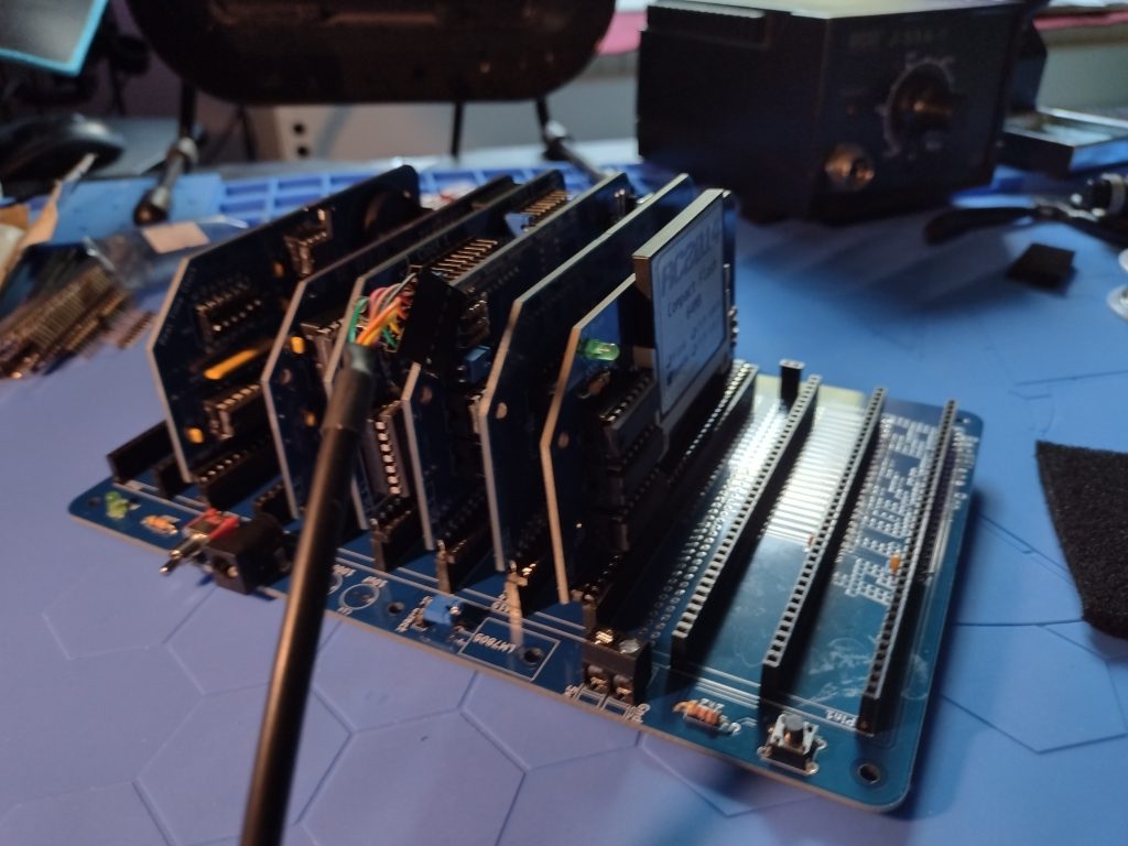
So I plugged all the ICs into their respective modules. I did the Z80 CPU first (only one IC, the actual Z80 CPU) on that module). Then the SIO/2 board, and so on. The only board I didn’t get completed is the Real Time Clock module – I don’t have a spare 2032 Coin Cell for it. Then I put the extended bus cards, the Z80 CPU, the Z80 SIO/2 board, and the DUAL Clock in the first three extended bus slots (Slots 5, 6, and 7). The ROM/RAM Memory module is in Slot 8, an extended bus slot but that board doesn’t need the extended bus. Finally I put the Compact Flash module in slot 4, a standard bus slot. I left the Real Time Clock out for the moment, given it doesn’t have it ‘s backup battery yet.
Finallly, I attached the FTDI cable to my computer and into the RC2014. I had to find the com port Windows assigned to it – which took it a while. It’s Com5. I fired up putty terminal software and configured a session to Com5 at 115200 bps and pressed reset on the RC2014. I got my first boot up results:
RC2014 Power up Boot – SUCCESS!!! It WORKS
SUCCESS!!! IT’S ALIVE
I was very happy, especially given the trouble the silver based solder gave me to start with (and two destroyed modules that I had to repurchase).
I did put the Real Time Clock (RTC) onto the board for the “photo op” where you can see the assembled system all together. But I didn’t power it up at that point (I thought about it so you could see the glowing power lights and such.
The full RC2014 assembled – so far.
While I had the system powered up, I launched the Z-System operating system (not the IBM Mainframe Z-System OS…) and explored the compact flash. I also tried out Microsoft Basic and made it print:
Hello,World!
RC2014 - is ALIVE!!!!!!
John Sandlin 250731
I meant to make it print the full year, 20250731, but made a typo and didn’t fix it the right way. The backspace key doesn’t work correctly in Basic.
What’s Next
There are a number of things I want to do still. I want to get the RC2014 Front Panel Kit (and a back panel kit too), a Sound Module that uses a vintage sound module that were popular with the MSX Z80 based computers, and a video / keyboard interface. The Front Panel Kit gives it a proper vintage Kit Computer look. My first computer was a HeathKit H89, which I built while studying MicroComputers through an NTS training course, but the Front Panel is even more primitive than the H89.
I might also want to see about making the RC2014 work with MSX software. That’s down the road a bit though.
I started the project using the silver based solder to try to keep it all RoHS. But the Silver Solder and me soldering wasn’t working out. I damaged to two of the project boards, The Serial IO and the Dual Clock boards. Silver Solder requires higher temperatures, I’m not the fastest solderer, and I melted a couple sockets so that pins fell out, and then I couldn’t get the silver solder to desolder and basically destroyed the boards. I had to order replacement PCBs and replacement components.
Now though, I have six RC2014 modules soldered up and just have the backplane left to go.
The six modules, starting top left and ending bottom right, are:
Top Row:
Dual Clock Module
The Dual Clock Module is an Enhanced Bus card (it has two rows of pins to the backplane). This is the system conductor, keeping the clock pulses that the CPU needs to execute the instructions in coordination with all the other components. This clock has to talk to all the other modules to keep them in Sync.
Compact Flash Storage Module
The Compact Flash Storage Module will hold all the software to run on the RC2014 computer. Back in the day computers like this might have used Paper Tape (like the Altair), or cassette audio tapes (like a Commodore Pet (which also later used floppy disks), or Floppy Disks (like many CP/M machines like mine will be), and maybe even a smallish hard disk drive. The Compact flash takes the place of the hard drive and can have a reasonably large capacity (if you can imagine 64 MB being reasonable), well compared to the 5 MB drives of the time.
Middle Row:
Z80 SIO/2 Serial Module
The Z80 SIO/2 Serial Module allows the Zilog Z80 CPU to talk to the outside world – like the User. It’s an old reference but the movie TRON, this would be the I/O Towers programs used to communicate with the Users. Back in the day when CP/M computers were The Big Deal, the SIO would connect to a serial terminal, like a DEC VT100, or to a keyboard and monitor if that computer had one, like modern computers and laptops do.
Real Time Clock Module
The Real Time Clock Module is purely optional and many CP/M computers in the early 1980s did not have one, you had to tell it the date and time each time you booted it up. I can have a script run in CP/M that reads the current date and time when the computer boots up. It’s handy to have your files time stamped.
Bottom Row:
Z80 CPU Module
The Z80 CPU Module is the brain of the system. The ZilogZ80 was an improvement over the Intel 8080 and was very popular in many CP/M computers. The Z80 is an 8-bit computer CPU that often came with incredibly small amounts of memory. 16K was common, along with 32K, 48K and even 64K. 64K was the most an 8 bit computer could typically address with a 16 bit address bus without resorting to “Bank Swapping.” A screen on these old computers could hold 80 text characters each on 25 lines. So imagine 8 of these screen pages, and that’s the 16K. All your software had to run in that memory, including the screen buffer (those 80×25 character lines of text), the operating system, the application (like Word Star, a popular word processor back then) and all your data. But memory was crazy expensive, so you did what you could in as little as you could afford. Until very recently, Zilog was still making the original 40 Pin DIP Z80 CPUs (albeit in slightly faster clock speeds). Zilog discontinuing the Z80 prompted me to do this project before the chips are all gone.
512K ROM / 512K RAM Memory Module
The 512K ROM / 512K RAM Memory Module takes advantage of Bank Switching to let the RC2014 address more than64K of memory. This is where the computer holds all the information it’s working on and with, the instructions in the programs it’s running, and anything it needs to complete the tasks it’s working on.
NEXT UP:
Tomorrow I’ll start work on the RC2014 Backplane Pro. This is the backbone of the computer, and also distributes power and facilitates communication between the module. Then the troubleshooting begins!
I have my first board for the RC2014 Z80 computer put together. This was a simple board, just a socket, four resisters, 1 capacitor, and a right angle header. A lot of small solders, though. Once I have a chance to validate the solders are good and I have the backplane wired, I will put the CPU in that socket. I just want to validate the power and ground are going to the right pins first. So I have a good deal of soldering to do before I get there.
RC2014 CPU Board front sideRC2014 CPU Board back side
I’ll probably work on the Dual Clock Card tomorrow. Every CPU needs a good clock, or two.
I got a 3D printed case from iCode.com for my MiSTer FPGA. It comes in several colors. The case I have is the “Crystal White” which is semi-translucent. It has little holes drilled to let the LED lights through but they shine right through the case anyway, so no light-pipes needed. It looks really nice, though I did have to file open a couple of the holes. The VGA connector needed more room, for example.
iCode.com Crystal White semi-translucent MiSTer FPGA case, system powered up and LEDs glowing.
I staged my MiniDexed project into a carboard box, pending getting my plastic case cut so I can finish in that. I’ll be using a PiSound Case from Blokas. I have an Actual PiSound and thought the case it is in would work for my MiniDexed, but I need to cut holes in it to pack the MiniDexed into it. But I want it done clean so I need some more parts for the project before it get’s it’s new home. Below is the current CardBoard MiniDexed.
Soon I’ll have a new project, the RC2014 Zed Pro, 8-bit Retro computer. It’s a modern take (from the Retro Challenge in 2014) on an 8-Bit Z80CP/M computer. My first computer was a HeathKitH89HDOS computer, where HDOS was a work alike system like CP/M. So this will be very similar, but without the built in CRT and Keyboard. It is made from currently manufactured parts, except the Zilog Z80 CPU which JUST went out of production late last year. Fortunately the creator of the kit has some Z80 chips still. But eventually those will run out, so I bought one and will have it in hand very soon.
I do have a soft spot in my heart for the Z80 because of my H89
My HeathKit H89 computer which I built for a National Technical Schools Micro Computers course
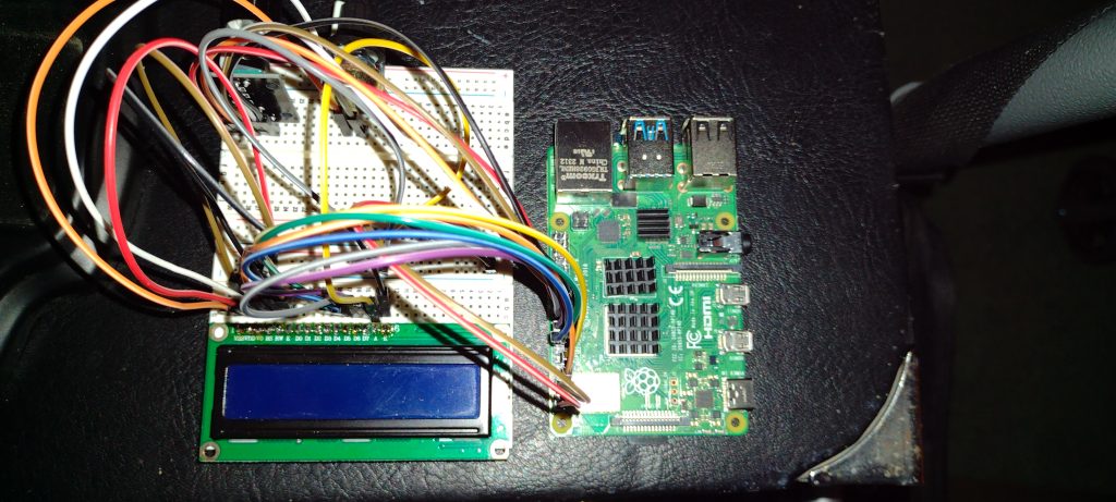
I started a new project to make a MiniDexed synth. The little synth recreates, to a large degree, the famed Yamaha DX 7 Synth (minus the keyboard and “front panel”). The MiniDexed uses a Raspberry Pi as the base, with a couple of knobs and a simple text display.
My MiniDexed Synth so far – prototype stage
I’ve ordered a project box to put the MiniDexed into which will take a while to arrive, they’re currently made when they’re ordered and then shipped, from Europe. I’m repurposing a PiSound case to make my project. The MiniDexed project has a “print-your-own” case available, but I don’t have a 3D printer so my choice was the PiSound case. The page for the project has a section showing their case design. That same page shows the wiring diagram I used to make the prototype.
I’ve tested the setup, and it does play music and emulates DX-7 voices nicely. I had to use a MIDI keyboard to control the synth and play some notes. In my picture above, you can see the simple 2 line by 16 character display, the rather well hidden two knobs – A continuous encoder to scroll through menus and select options, and a contrast potentiometer, and of course the Raspberry Pi 4.
I will be using connector headers to make the wiring harness so that the parts can be installed in sections so I can open the project case as needed. One 16 pin header for the display which connects to a 2×20 pin header to connect to the Raspberry Pi GPIO pins. That 2×20 pin header will also connect a five pin header to the continuous encoder, and a 2 pin connector for the contrast potentiometer.
Once completed, the MiniDexed will operate as eight sound engines, each capable of 16 simultaneous notes, much like a Yamaha TX 816 Rack module. The TX 816 put 8 DX-7 Sound Engines in a rack mountable cage. That’s 128 notes at a time via the 8 sound engines (they can be all the same voice, or 8 different, or a mix between, at 16 notes from each sound engine). All controlled by MIDI messages.
I found all the parts to a DIY Music Synthesizer – The ArduTouch Music Synthesizer by Cornfield Electronics. It uses an Arduino UNO type microprocessor. I bought the kit in 2017. I got the decent Soldering Station so I was ready to put it together. I ran to the web page for the ArduTouch and got the assembly instructions. So – Here is the finished results:
ArduTouch Music Synthesizer, batter pack and FTDI cable.
I should emphasize that this is an Arduino UNO type setup, the board is different, but it does use the same Atmel ATmega328P main chip. It makes rather interesting sounds. The default synth program is called Thick. There are several other programs in the github repository.