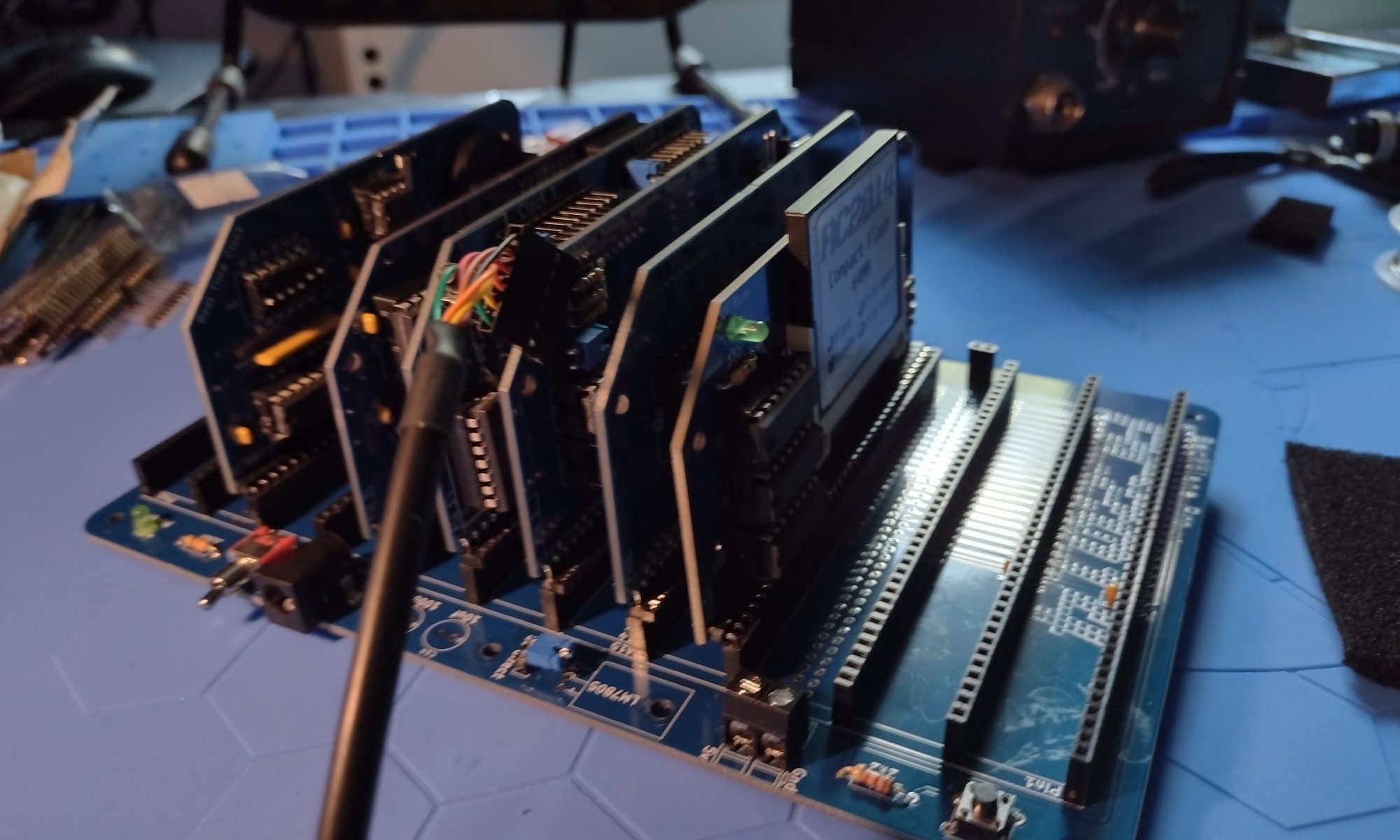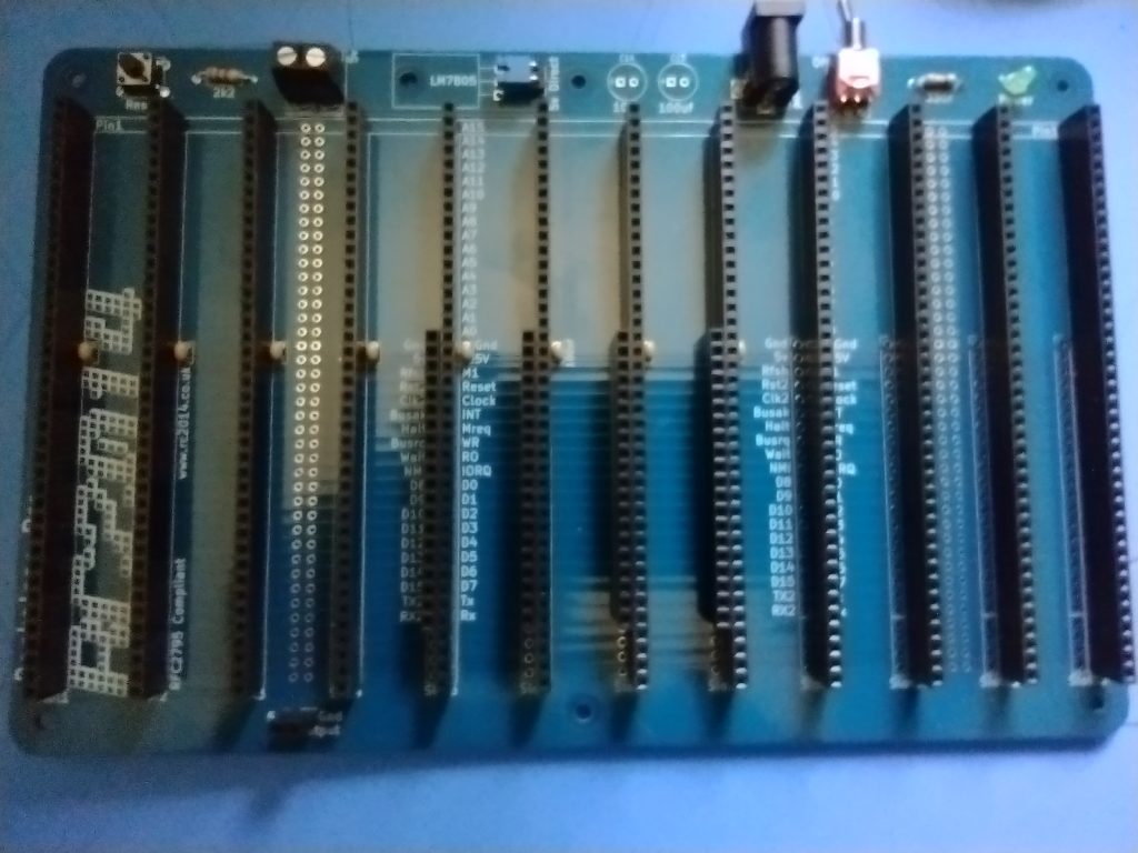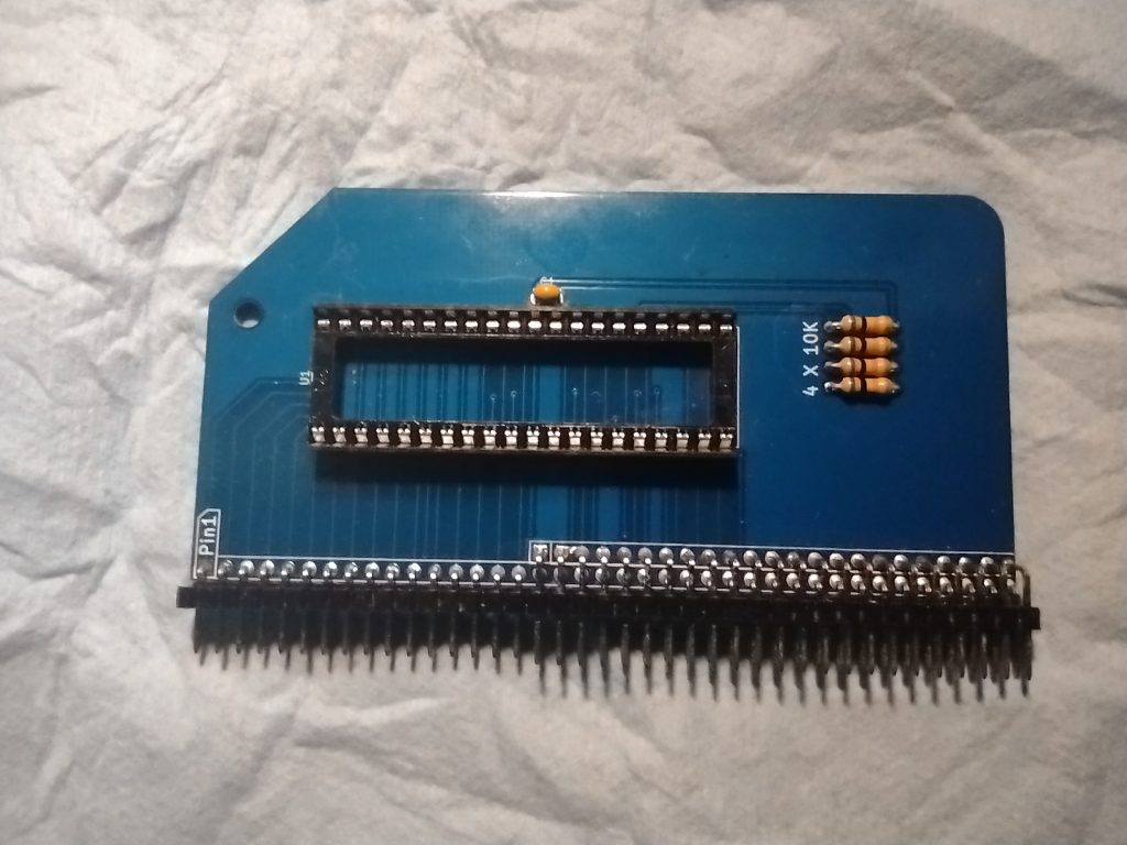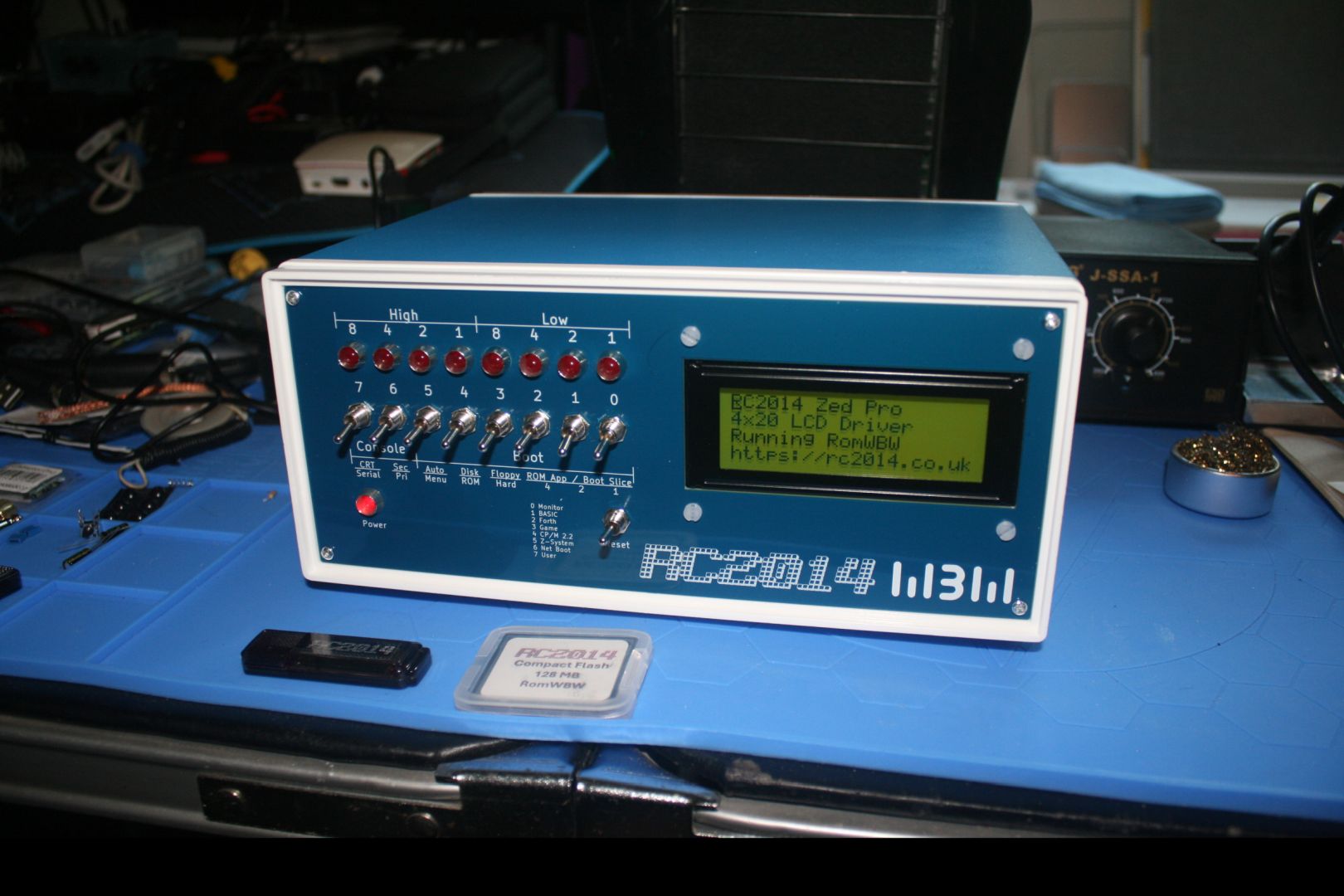
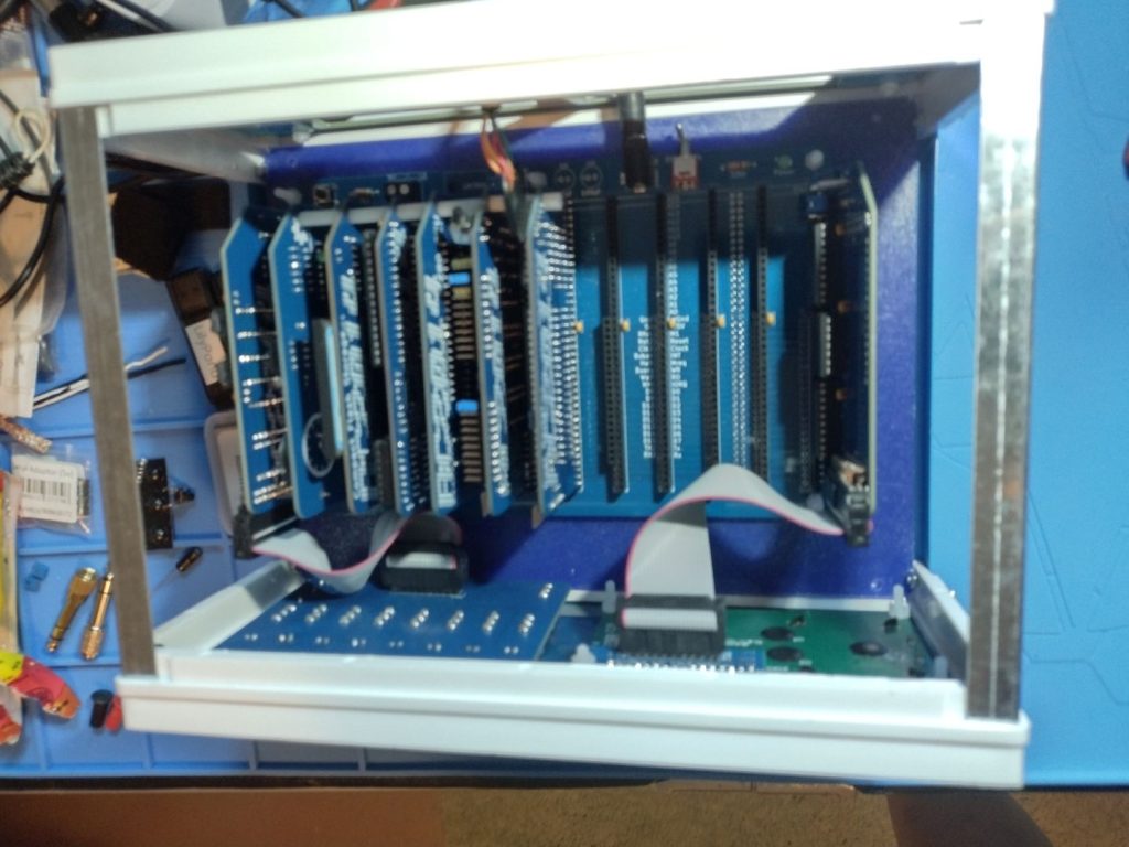
I received the “Front Panel” and “Rear Panel” Kits for my RC2014 Z80 Computer. These panels are specifically designed for the Blue Box 110x250x190 mm project case, which I had purchased even before I got the initial kit to create the RC2014. I spent the last few days soldering and assembling the panels.
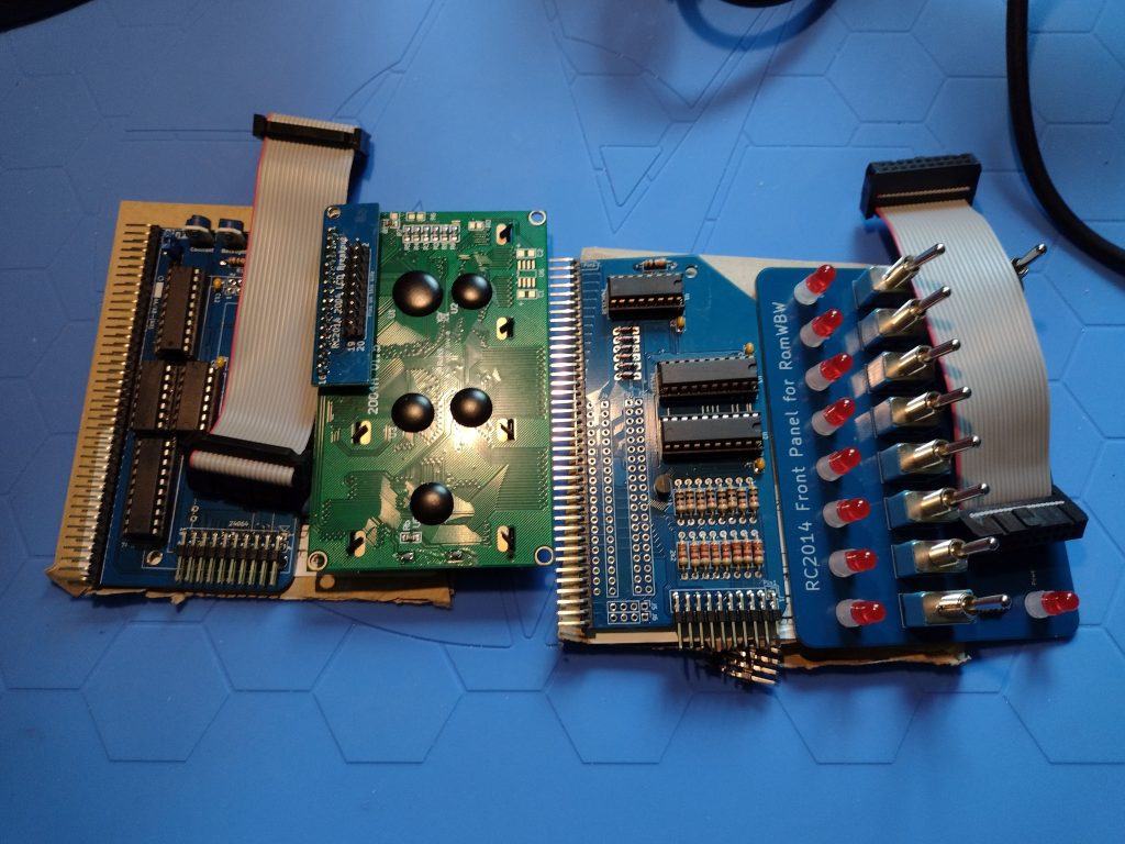
You can see little tabs poking up through the back of the LCD panel. Under the little interface board that converts the 2×20 ribbon connector to the 16 pin the module needs is a tab that poked up into the pins of the little interface. It caused problems and I had to clip off that one tab. The Front I/O panel was also a problem, I soldered its ribbon cable header to the wrong side of the board, I had to desolder the header and flip it around behind the front panel so the ribbon cable could connect. My reading skills must be slipping. Though I don’t think the instructions mentioned the tabs on the LCD Display poking into the pins of the cable header.
There was a good bit of head scratching before I fixed those problems. But in the end, the front panel I/O and LCD Display are working well.
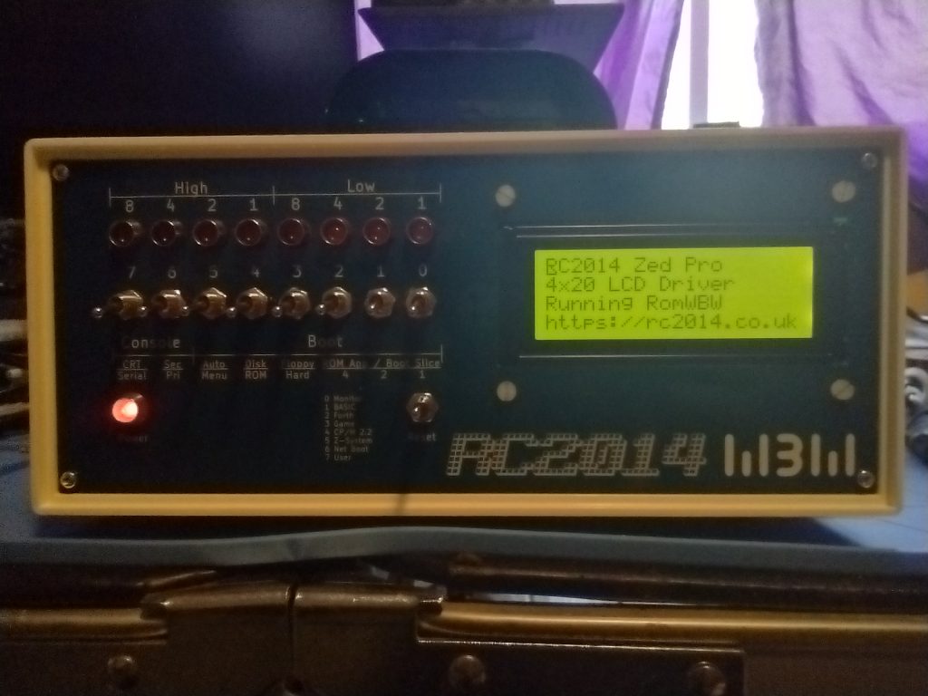
The switches on the Front Panel I/O control the boot up. There are several choices for how to boot.
- First is the Small Computer Monitor, a program that allows direct access to the CPU registers and memory.
- Second is a version of Microsoft BASIC for 8080 (and Z80) microprocessors. This would be similar to how many 1970s and 80s computers would boot straight into the BASIC language interpreter (Such as the Commodore 64).
- Third Boot option is a FORTH Language Interpreter. I have no idea how to use FORTH, at least at the moment.
- The Fourth Boot option is a simple game called 2048.
- The Fifth boot option is CP/M 2.2, Digital Research’s famed operating system for personal computers of the late 1970s and into the 1980s and that a version of was offered to IBM for the IBM PC. But Digital Research didn’t like the restrictions IBM wanted (and which Microsoft found a way around when the licensed MS-DOS to IBM).
- The Sixth option is Z-System, an enhanced version of CP/M for the Z80 CPU (and the one I use the most).
- The Seventh is a “Net Boot” which won’t work since I don’t have the RC2014 on the network.
- And the final (eighth) front panel option is a User ROM boot, but I haven’t put in a User ROM so no booting from it either.
The Front panel also has an option to boot from the hard drive (in my case a Compact Flash drive like I have in my Canon EOS DSLR). There are 5 “slices” to boot from the current hard drive.
- Slice 2.0 boots CP/M-80 v2.2
- Slice 2.1 boots ZSDOS v1.1
- Slice 2.2 boots ZSDOS v1.1 (yup, I’m wondering if I messed something up)
- Slice 2.3 boots CP/M-80 v3.0 with Banked Memory
- Slice 2.4 boots ZPM3 with Banked Memory (compatible with CP/M+)
I made a second Compact Flash (CF) for learning how to customize the system. I’m still using the original Compact Flash drive that came with the kit, though. The second CF drive has several Infocom Games, like Zork, or Hitchhhiker’s Guide to the Galaxy, the classic Colossal Cave Adventure, and a few others. I also have HiTech-C and z80ASM programming tools, WordStar and ZDE, and stuff I’ve already forgotten.
The install of the Rear Panel Kit was simple. I got the blank version, it has blank cover for the holes where cables and connectors will eventually go. I’ll get those as I need them. Things like the FDTI adapter, and audio ports, maybe a video port, and so on.
Next up? I think a sound card, probably this one Why-Em-Ulator.