I started the project using the silver based solder to try to keep it all RoHS. But the Silver Solder and me soldering wasn’t working out. I damaged to two of the project boards, The Serial IO and the Dual Clock boards. Silver Solder requires higher temperatures, I’m not the fastest solderer, and I melted a couple sockets so that pins fell out, and then I couldn’t get the silver solder to desolder and basically destroyed the boards. I had to order replacement PCBs and replacement components.
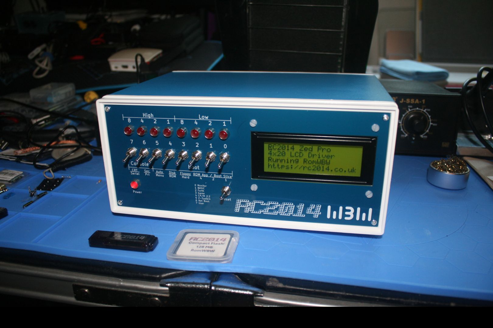
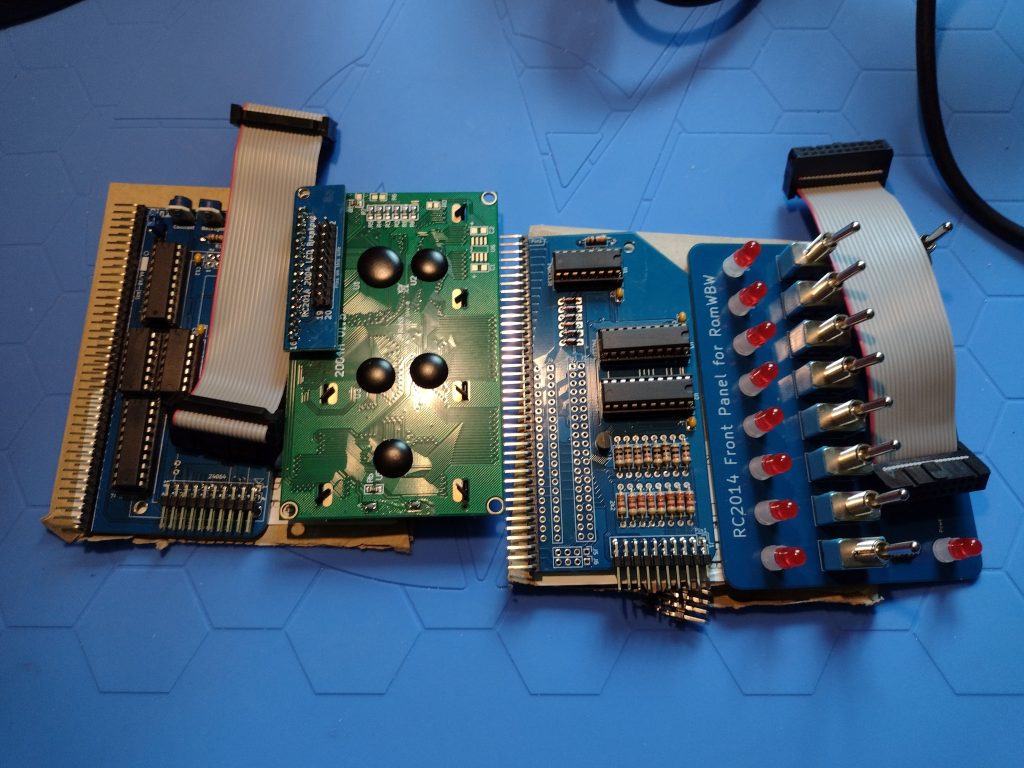
Now though, I have six RC2014 modules soldered up and just have the backplane left to go.

The six modules, starting top left and ending bottom right, are:
Top Row:
Dual Clock Module
The Dual Clock Module is an Enhanced Bus card (it has two rows of pins to the backplane). This is the system conductor, keeping the clock pulses that the CPU needs to execute the instructions in coordination with all the other components. This clock has to talk to all the other modules to keep them in Sync.
Compact Flash Storage Module
The Compact Flash Storage Module will hold all the software to run on the RC2014 computer. Back in the day computers like this might have used Paper Tape (like the Altair), or cassette audio tapes (like a Commodore Pet (which also later used floppy disks), or Floppy Disks (like many CP/M machines like mine will be), and maybe even a smallish hard disk drive. The Compact flash takes the place of the hard drive and can have a reasonably large capacity (if you can imagine 64 MB being reasonable), well compared to the 5 MB drives of the time.
Middle Row:
Z80 SIO/2 Serial Module
The Z80 SIO/2 Serial Module allows the Zilog Z80 CPU to talk to the outside world – like the User. It’s an old reference but the movie TRON, this would be the I/O Towers programs used to communicate with the Users. Back in the day when CP/M computers were The Big Deal, the SIO would connect to a serial terminal, like a DEC VT100, or to a keyboard and monitor if that computer had one, like modern computers and laptops do.
Real Time Clock Module
The Real Time Clock Module is purely optional and many CP/M computers in the early 1980s did not have one, you had to tell it the date and time each time you booted it up. I can have a script run in CP/M that reads the current date and time when the computer boots up. It’s handy to have your files time stamped.
Bottom Row:
Z80 CPU Module
The Z80 CPU Module is the brain of the system. The Zilog Z80 was an improvement over the Intel 8080 and was very popular in many CP/M computers. The Z80 is an 8-bit computer CPU that often came with incredibly small amounts of memory. 16K was common, along with 32K, 48K and even 64K. 64K was the most an 8 bit computer could typically address with a 16 bit address bus without resorting to “Bank Swapping.” A screen on these old computers could hold 80 text characters each on 25 lines. So imagine 8 of these screen pages, and that’s the 16K. All your software had to run in that memory, including the screen buffer (those 80×25 character lines of text), the operating system, the application (like Word Star, a popular word processor back then) and all your data. But memory was crazy expensive, so you did what you could in as little as you could afford. Until very recently, Zilog was still making the original 40 Pin DIP Z80 CPUs (albeit in slightly faster clock speeds). Zilog discontinuing the Z80 prompted me to do this project before the chips are all gone.
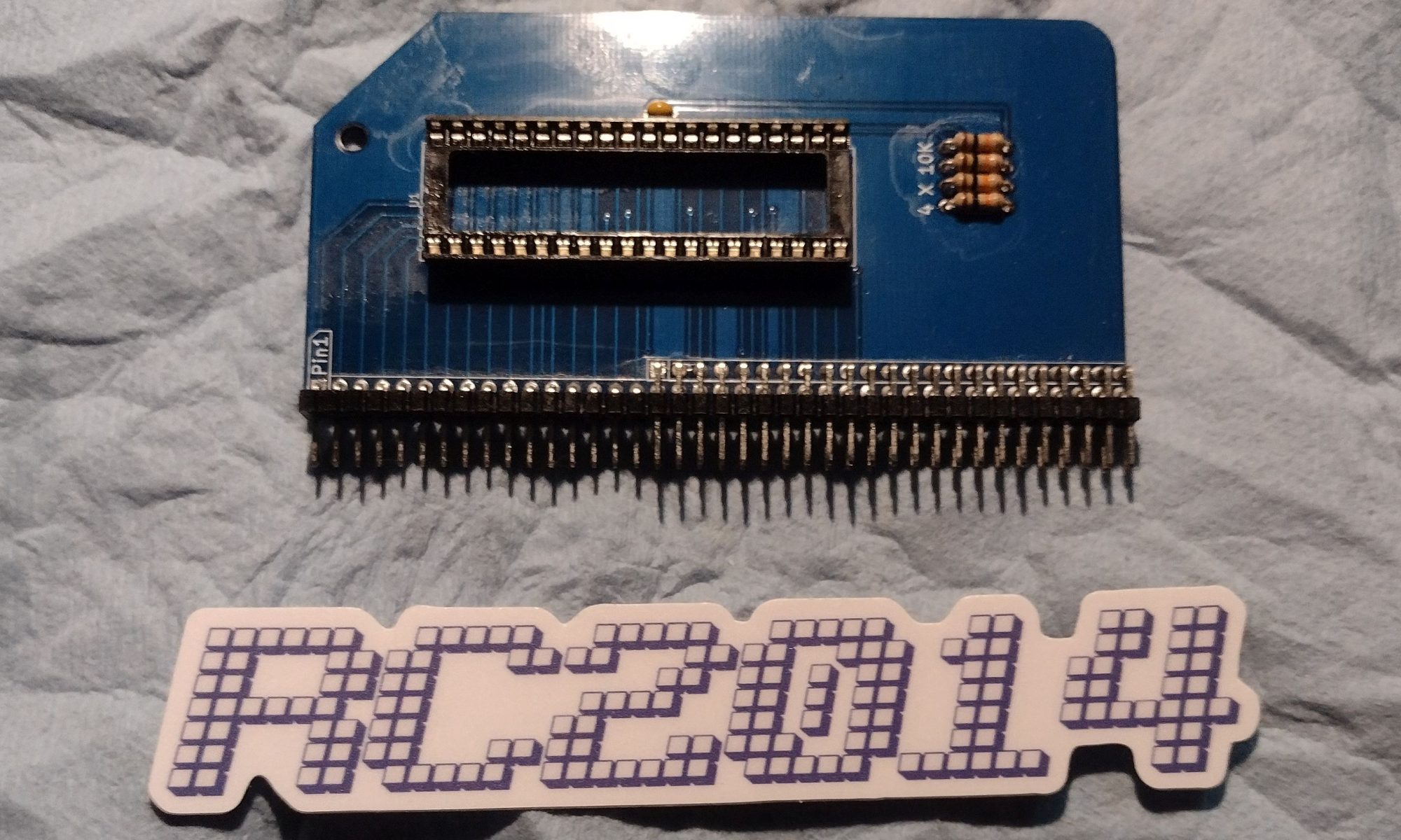
512K ROM / 512K RAM Memory Module
The 512K ROM / 512K RAM Memory Module takes advantage of Bank Switching to let the RC2014 address more than64K of memory. This is where the computer holds all the information it’s working on and with, the instructions in the programs it’s running, and anything it needs to complete the tasks it’s working on.
NEXT UP:
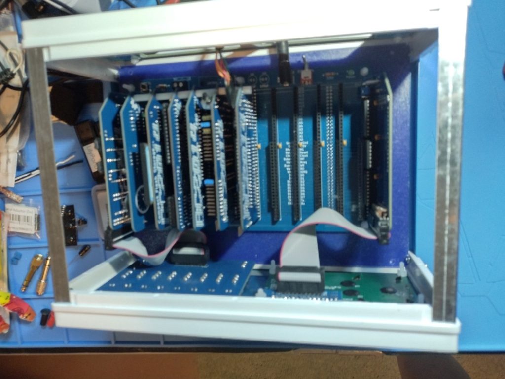
Tomorrow I’ll start work on the RC2014 Backplane Pro. This is the backbone of the computer, and also distributes power and facilitates communication between the module. Then the troubleshooting begins!